Unfolding Workshop
The Unfolding Workshop enables you to define the UV-mapping of complex surfaces.
The unfolding workshop interface consists of four zones:
- The main tool bar,
- The 2D UV zone,
- The 3D Geometry zone,
- The Surfaces zone.
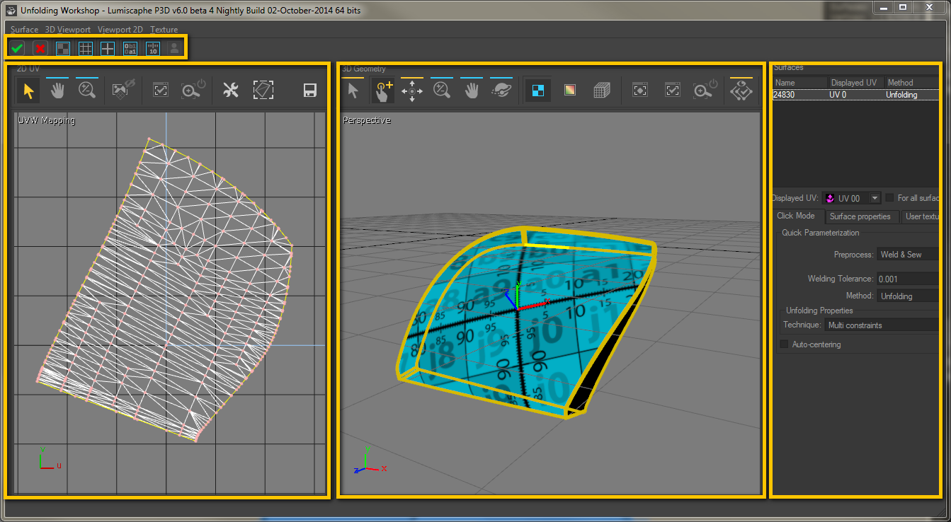
Main Toolbar
The main toolbar contains two buttons validate or cancel the adjustments made in the unfold workshop, as well as six background texture options to make it visually easier to understand the unfold procedure that has taken place.
![]()
![]()
![]()
![]()
![]()
![]()
![]()
![]()
![]() : The Validate button is for confirming and accepting the UV changes that have been made in the unfold workshop.
: The Validate button is for confirming and accepting the UV changes that have been made in the unfold workshop.
![]() : The Cancel button is for cancelling and exiting the unfold workshop changes, disregarding the UV modifications that have been made.
: The Cancel button is for cancelling and exiting the unfold workshop changes, disregarding the UV modifications that have been made.
![]()
![]()
![]()
![]()
![]()
![]() : The texture options change the background and surface texture for the selected unfolded surfaces.
: The texture options change the background and surface texture for the selected unfolded surfaces.
|
Figure 61 :
|
Figure 62 :
|
|
Figure 63 :
|
Figure 64 :
|
|
Figure 65 :
|
Figure 66 : |
![]() : The User-defined texture toggle is for enabling/disabling the background texture of your choice.
: The User-defined texture toggle is for enabling/disabling the background texture of your choice.
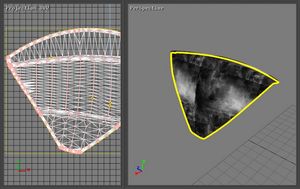
Figure 67 :
![]() : User-Defined
: User-Defined
The procedure for loading a texture file of your choice is explained below in the User Texture subsection of the Surfaces section.
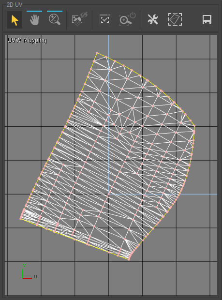
2D UV Zone
The 2D UV zone contains an interactive 2D view in which the surface is displayed when it is unfolded, as well as several special tools.
| Icon | Operation | Description |
|---|---|---|
|
|
Zoom | Zoom in the 2D view. |
|
|
Pan | Pan in the 2D view. |
|
|
Background | Enable/disable the display of the background textures (see the Main Toolbar subsection). |
|
|
Zoom Selection to Fit | Reframe the 2D view and center it on the selected unfolded surface. |
|
|
Auto Zoom Selection to Fit | Enable/disable the automatic reframing of the view on the unfolded surfaces when they are selected. |
|
|
Edit parametrization margin | Open an editor for defining margins around the unfolding so that it will be easier to use after export. |
|
|
Show bounding-box | Enable/disable the display of the previously defined margins. |
|
|
Export parameterization | Open an editor for configuring and then exporting the 2D image of the unfold that has taken place. In this way you can use your surface-unfolding work with graphic creation tools to edit textures that are perfectly suited to the programming of your surfaces. |
Defining a Constraint
The user can convert the markers previously set on the surface in the 3D view into constraints either by simply left-clicking in the UVW 2D window or by using the Convert Markers to Constraints option accessed by right-clicking in the 2D view.
- For a surface unfolded using the One-click option in the Hit mode tab of the Surfaces panel, the three vertices of the triangle the marker is set on will be converted into constraints.
- For a surface unfolded with the Multi-constraints option, the vertices of all triangles containing a marker will be transformed into constraints.
- When a surface was unfolded with the Follow Boundary option, all vertices on the corresponding boundary are converted into constraints.
These constraints are represented by yellow and red dots in the UVW mapping. Any point thus highlighted represents a constraint.
Any point in the UVW mapping may be moved in order to create a deformation using the Select and Translate tool from the UV 2D toolbar. The parameterization is updated in real time. Moving a point with no constraint assigned to it defines a new constraint. The point is then highlighted.
Modifying a Constraint
In order to modify a constraint, the Select and Translate tool must be activated. The highlighted point may be set to another position by dragging it, thus modifying the constraint.
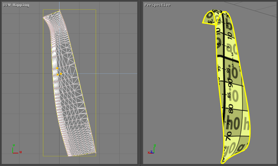
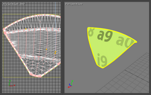
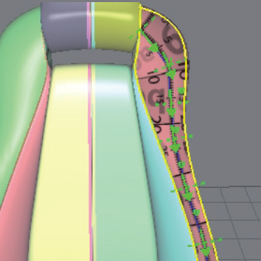
Figure 68 : UV mapping of a surface unfolded using the one-click method and corresponding 3D view.
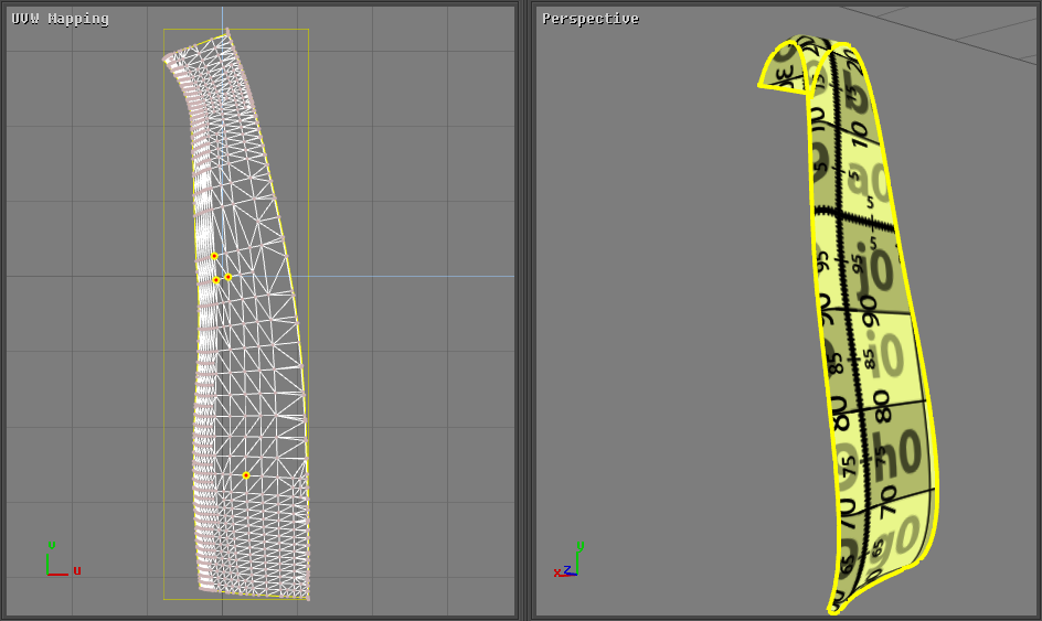
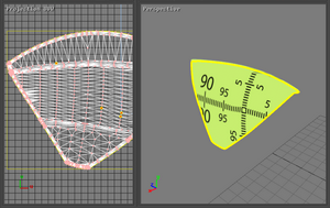
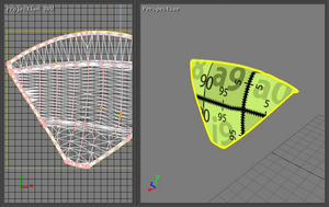
Figure 69 : UV mapping of the surface after an additional constraint was added and corresponding 3D view.
Releasing a Constraint
In order to release the constraint set on a point, the option Release Constraint on Selected Point must be chosen. This option is accessible by right-clicking on the corresponding highlighted point.
All the constraints set on the UV mapping can be released at the same time by using the option Delete All Markers accessible by right-clicking in the UVW mapping view.
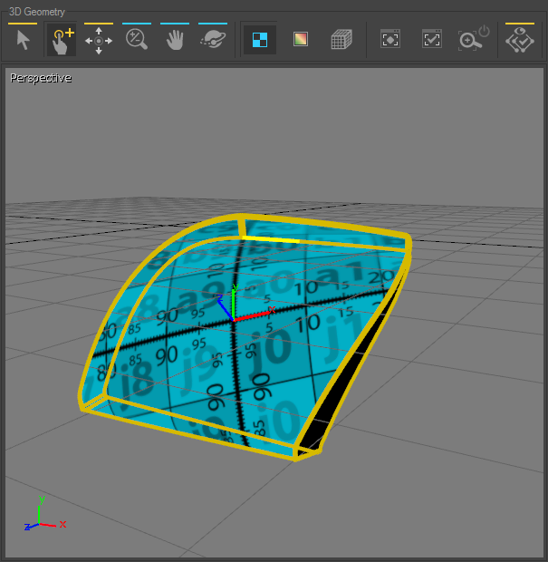
3D Geometry Zone
The 3D Geometry zone contains an interactive 3D view in which the surfaces to be unfolded and several tools for unfolding and manipulating the surfaces are displayed.
| Icon | Operation | Description |
|---|---|---|
|
|
Select | Select surfaces. |
|
|
Quick Assignment | Create markers by clicking directly on the surface. |
|
|
Move Marker | Select and move a marker on the unfolded surface. |
|
|
Zoom | Zoom in the 3D view. |
|
|
Pan | Move around in the 3D view. |
|
|
Orbit | Control the rotation of the 3D view in order to observe the surfaces from different points of view. |
|
|
Set Render to Texture | View the background textures of an unfolded surface. |
|
|
Set Render to Deformation | View a highlighted distribution of the physical forces associated with the deformation of the unfolded surfaces. |
|
|
Show Wireframe | Enable/disable the display of the surfaces' wireframe. |
|
|
Zoom to Fit | Reframe and center the 3D view on of the surfaces in the unfolding workshop. |
|
|
Zoom Selection to Fit | Reframe and center the 3D view on a selection. |
|
|
Auto Zoom to Selection to Fit | Enable/disable the automatic reframing of the view on the unfolded surfaces when they are selected. |
|
|
3D Selection Only | Limits the display of the 3D view to the surface being unfolded. To return to a view of all selected surfaces, click on this button again. |
Surfaces Zone
The Surfaces zone contains an area for exploring the surfaces involved, and three menu tabs for configuring the methods for unfolds and viewing them.
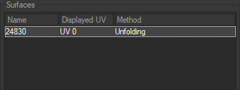
The area for exploring the surfaces lets you select the surfaces by their name and view the unfolding method used. (The selected surface is highlighted. )
Each surface can combine up to 32 separate unfolding sets. At the bottom of the box, Displayed UV channel allows you to choose the set of UV targeted by the unfolding.
This zone is followed by several tabs which give access to the workshop settings.
Click Mode
The Click Mode tab provides access to the fast unfold general options.
Preprocess provides access to three types of preparation: None, Sew and Weld & Sew.
| Preparation | Description |
|---|---|
| None | Uses the current topology of the surface. |
| Sew | Carries out a sewing operation on the edges. |
| Weld & Sew | Carries out a sewing and joining operation on the edges. |
Welding Tolerance assigns a numerical value to the tolerance of the CV's when the Weld & Sew mode of preprocess is selected.
Method provides access to three types of unfolding methods: None, Copy and Unfolding.
| Method | Description |
|---|---|
| None | Remove and cancel the previous unfolding work. |
| Copy |
Is used to retrieve an existing unfolding method.
In Copy mode, the unfolding workshop offers the choice of currently-defined UV sets. A drop-down menu allows you to browse the UV sets and select the most suitable set for unfolding the selected surfaces. |
| Unfolding |
Create an unfolding of the surface using the 3D view.
Unfolding Properties: Technique provides access to three different unfolding techniques: One click, Multi constraints and Follow boundary. These techniques are described below. |
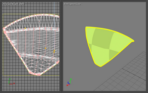
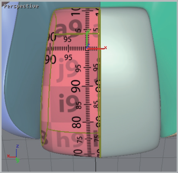
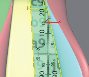
- One click: is for creating a new unfold with just one click on the surface to be unfolded. The origin of the unfold is on the surface at the precise location where the click has been made. With this technique, the orientation of the texture is always positioned so that the y axis of the texture is parallel to the vertical edges of the 3D view.
|
|
|
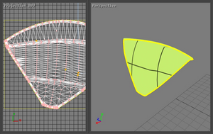
- Multi constraints: is for assigning several markers to the unfold so that it precisely follows the form of the surface.
|
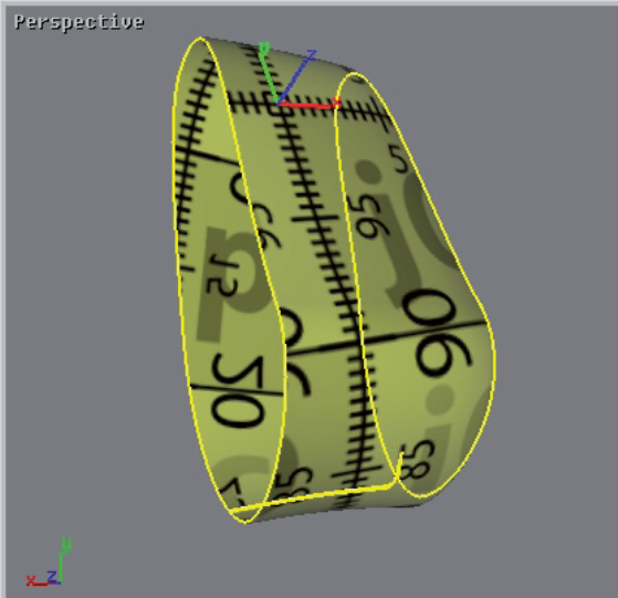
Figure 70 : One click method. |
Figure 71 : Multi-constraints method. |
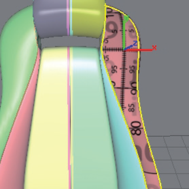
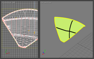
- Follow boundary: is for constraining the unfold to a specific edge of a surface. Two markers are necessary for this unfolding technique.
|
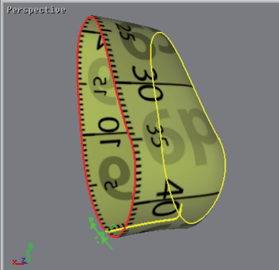
Figure 72 : One click method. |
Figure 73 : Follow boundary method. |
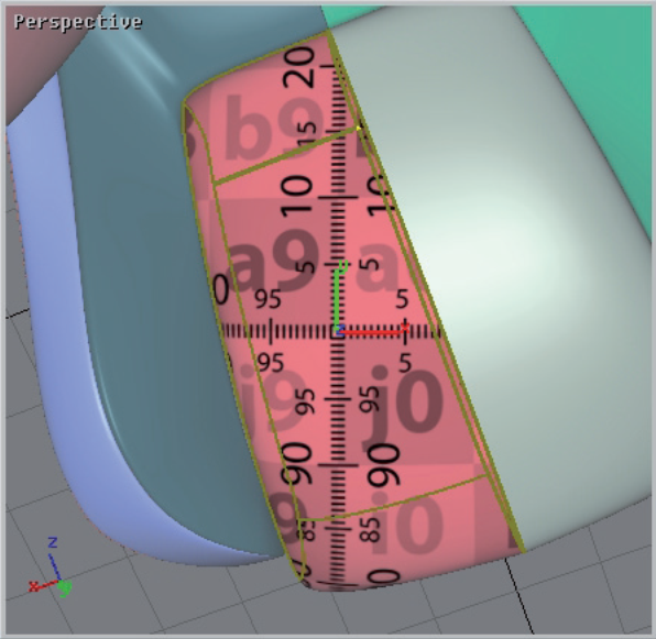
- The Auto centered option is for positioning the origin of the texture in the center of the surface, regardless of where the click has been performed.
|
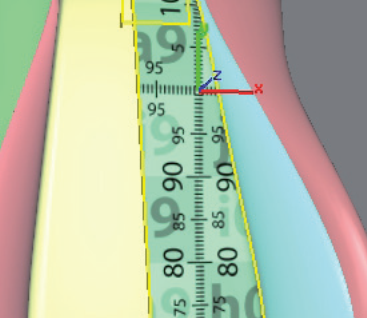
Figure 74 : Auto-centered disabled. |
Figure 75 : Auto-center enabled. |
Surface Properties
The Surface properties tab provides access to the unfold options depending on the selected unfolded surface.
![]() : The Reset button is for re-establishing the initial unfold assigned to the surface.
: The Reset button is for re-establishing the initial unfold assigned to the surface.
The Parametrization frame provides the same unfolding options as in the Hit mode tab (see the Hit Mode Tab section).
When the unfolding methods Multi constraints or Follow boundary are chosen, the placement of markers that define the constraints are handled using the following buttons:
| Icon | Use | Description |
|---|---|---|
|
|
Place marker | Place a new marker at the clicked location on the selected surface |
|
|
Delete all markers | Delete the markers created with the Multi constraints unfolding technique. |
|
|
Swap boundary markers |
Reverse the direction of the markers created with the Follow boundary unfolding technique. |
|
|
Apply | Confirm the adjustments made on the selected surface. |
The UV Transformation frame is for positioning the texture using numerical values.
The Automatic centering option is for positioning the origin of the texture in the center of the surface (see the Surfaces Zone section).
User Texture
The User texture tab provides access to the properties of a user texture.
![]() : The Open texture button is for loading a texture from your documents.
: The Open texture button is for loading a texture from your documents.
![]() : The Reload texture button is for updating the loaded image.
: The Reload texture button is for updating the loaded image.
The Dimensions frame is for assigning metric values to the texture dimensions.
![]() : The Reset texture dimensions button is for canceling the values assigned to the texture dimensions and for returning to the initial values.
: The Reset texture dimensions button is for canceling the values assigned to the texture dimensions and for returning to the initial values.
The Preview frame is for viewing the image loaded for the texture.
